Speco VM-905C CRT Monitor RGB Mod
Introduction
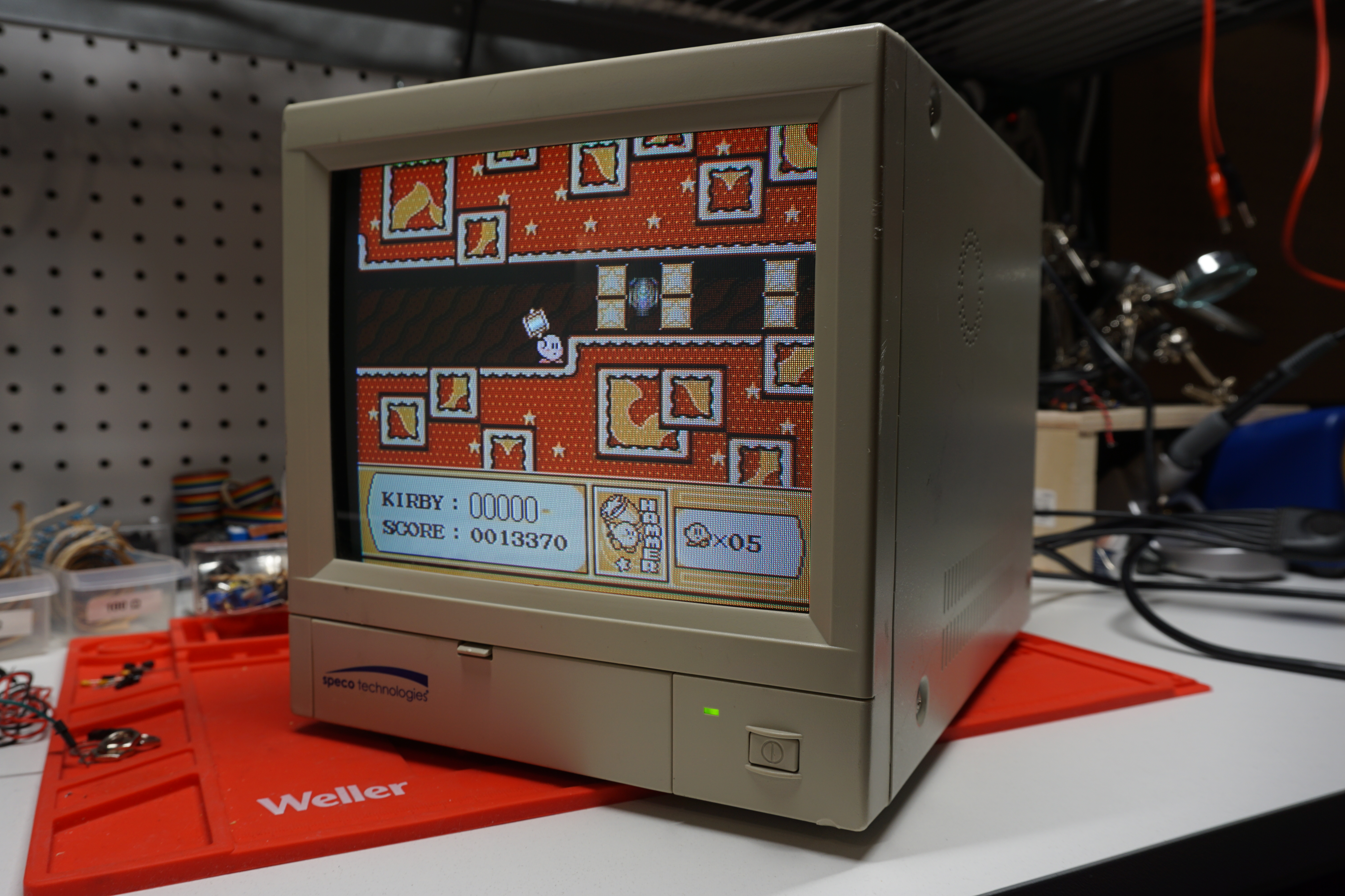
I recently purchased a 9” Speco CCTV monitor on eBay. I was searching for a small CRT display for my workbench with composite and S-Video, and this one fit the bill nicely! This little monitor has a flat CRT and the spec sheet advertises a resolution of 500 TVL (although based on the dot pitch of the tube itself, I think it’s more in the 250-300 range). It produces a bright, sharp picture, and retro games look great! As an added bonus, this monitor is very easy to RGB mod, turning it into a great budget PVM alternative.
Disassembly
Taking a look inside, this monitor is densely packed. The neck board on the crt is pressed right up against the back of the case, and that vertically mounted power supply is definitely something to be cautious around! Those large capacitors can store quite a charge.
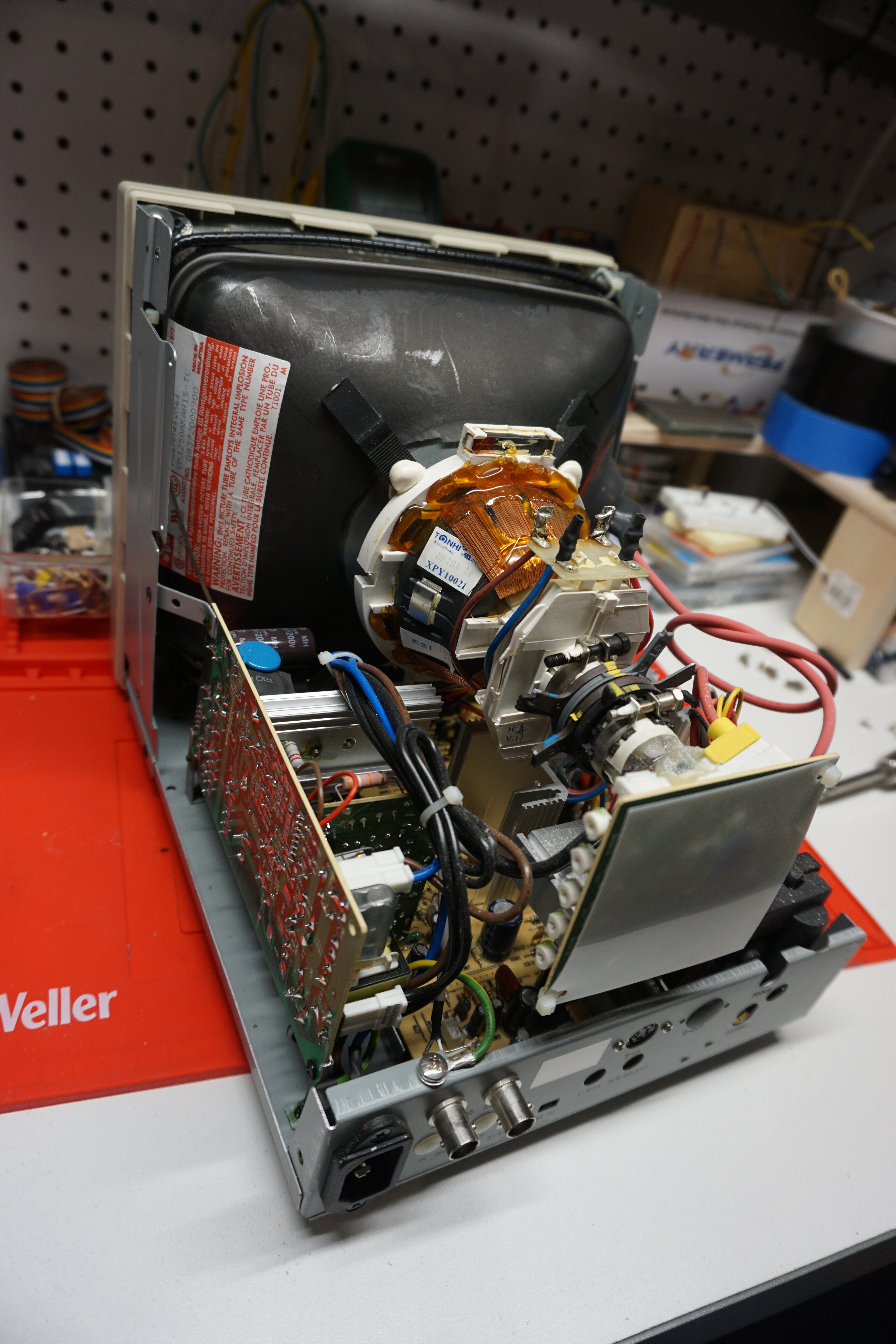
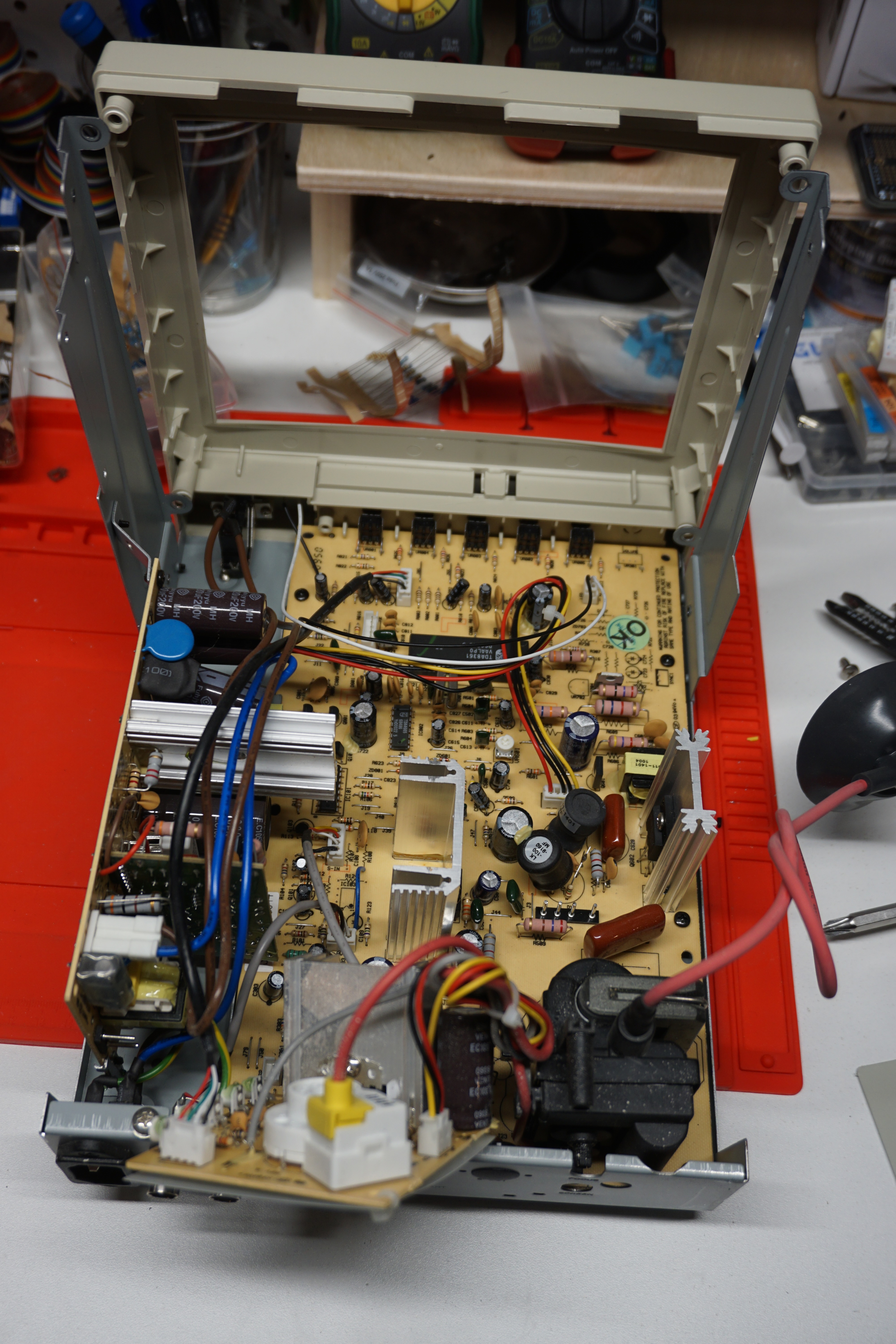
Unfortunately, getting to the main board is not a simple task. I had to remove the CRT first before I had the clearance to free the board from the chassis.
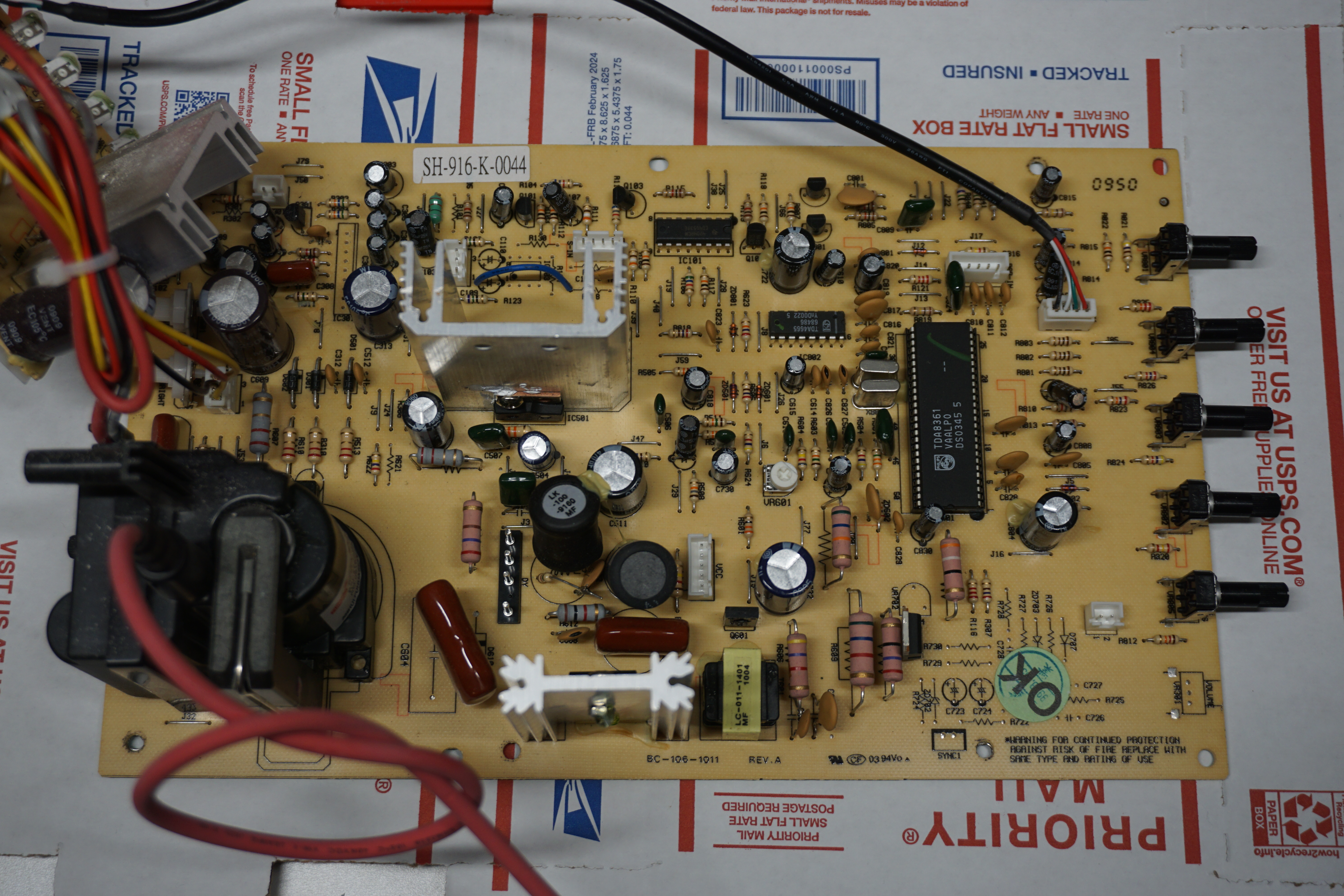
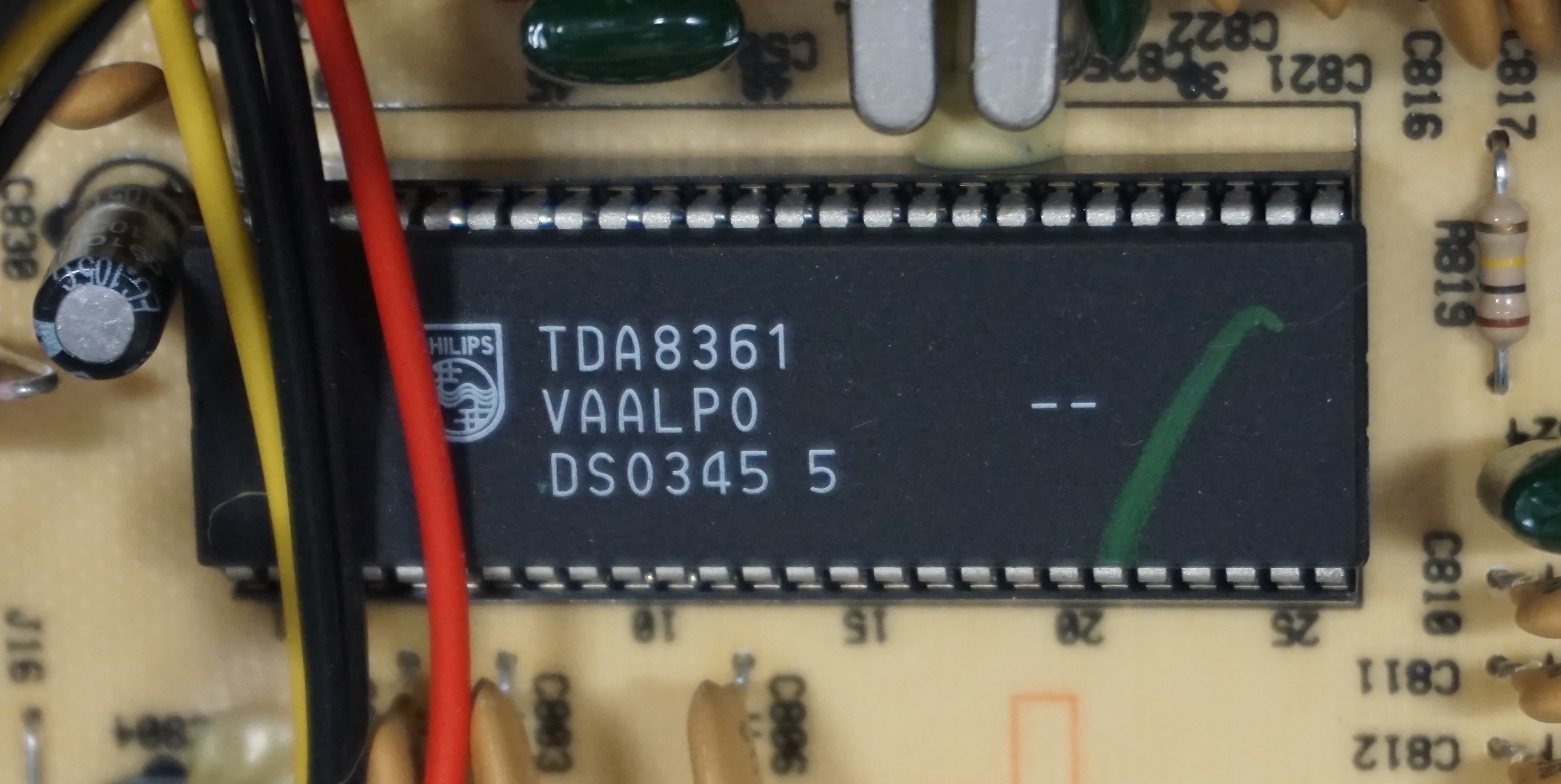
The good news is that this monitor uses a versatile jungle chip, the Philips TDA8361. With this chip, an RGB mod via direct injection will be very easy to perform!
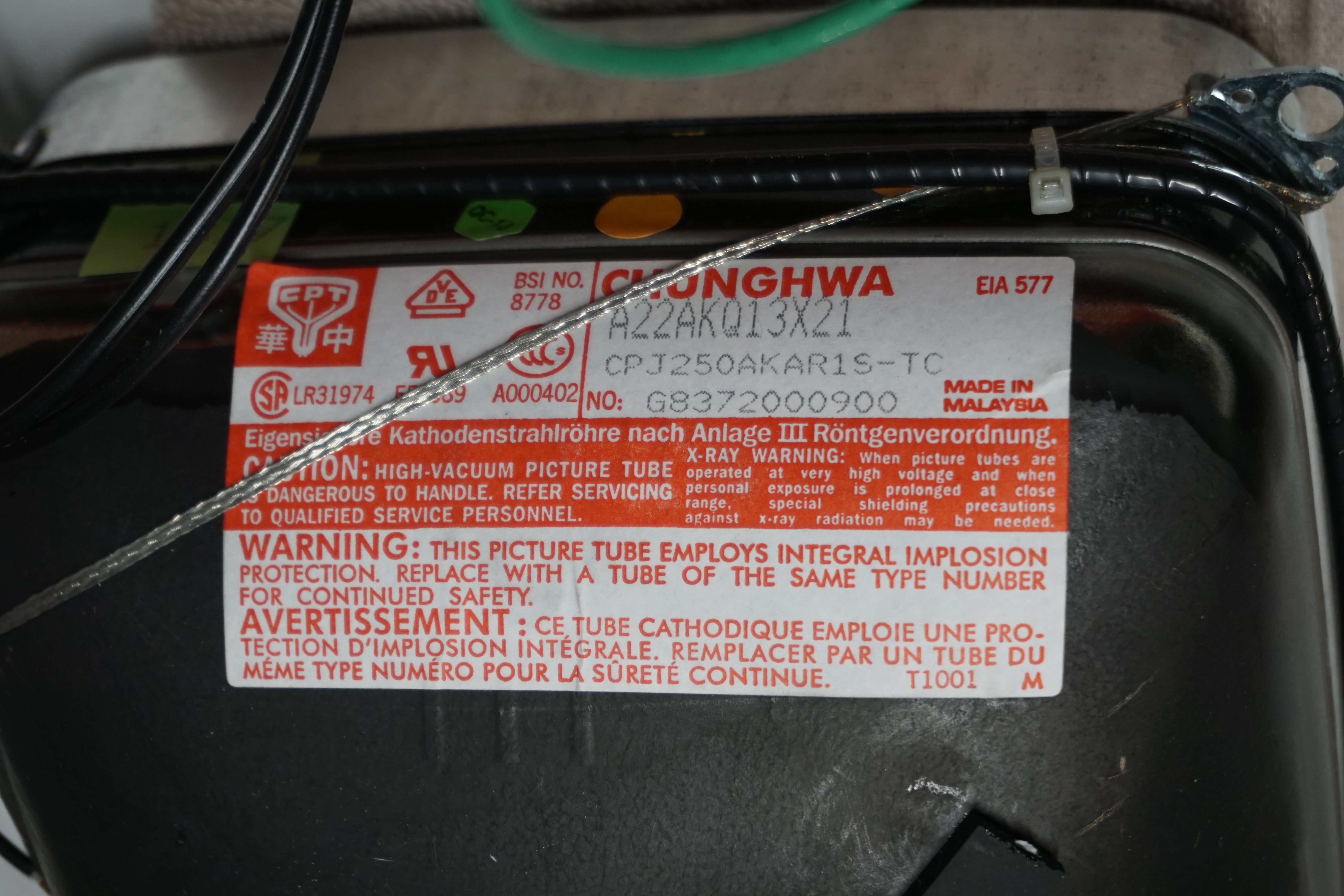
The CRT was made by Chunghwa, model A22AKQ13X21. According to the CRT Database, the A22AKQ13X was also used in video monitors from Ikegami and JVC. These other monitors were rated for 280-300 TVL so I think Speco’s claim of 500 TVL is a bit optimistic. That said, this tube is able to resolve a fair amount of detail and I suspect it has a finer dot pitch than a similarly sized television grade tube.
Performing the mod
According to the TDA8361 data sheet, the RGB blanking is pin 21 and the red, green, and blue inputs are pins 22, 23, and 24 respectively. When I went to trace out these lines on the main board, I was surprised to see that these pins where already connected to a header on the board! Complete with 75 ohm resistors for input termination and AC coupling capacitors, already populated. So, this will be a very easy mod…
Step 1 - Connect to the RGB Header
As stated, the coupling and termination components are already present on the board:
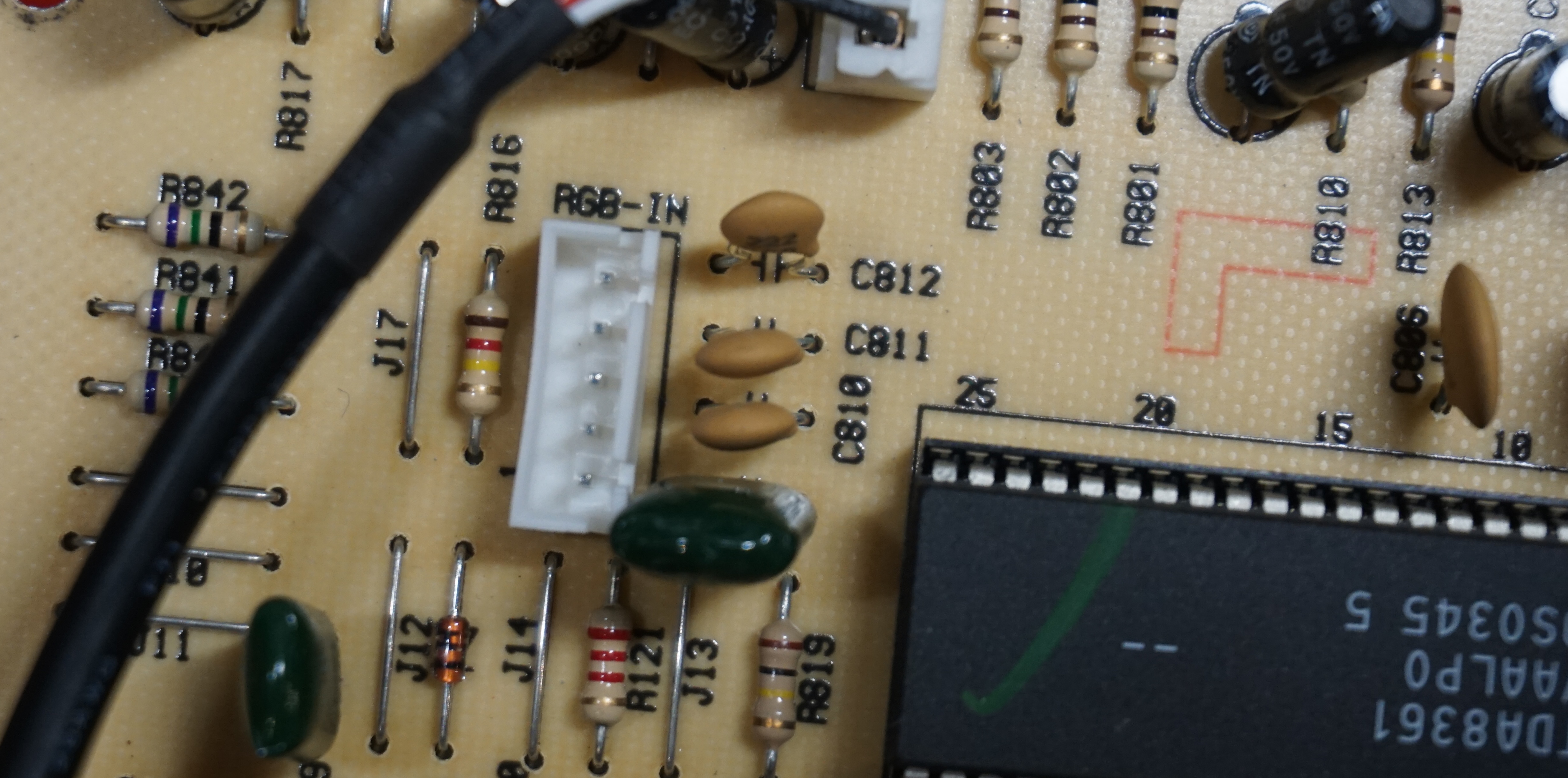
So the only thing left to do is connect to the 5-pin header. The pin out is the following:
PIN 1 - GND
PIN 2 - Composite Sync
PIN 3 - Red
PIN 4 - Green
PIN 5 - Blue
I was able to find a ribbon cable with a connector that fit the header on the board. I extended the length and soldered my BNC jacks on the end for testing:
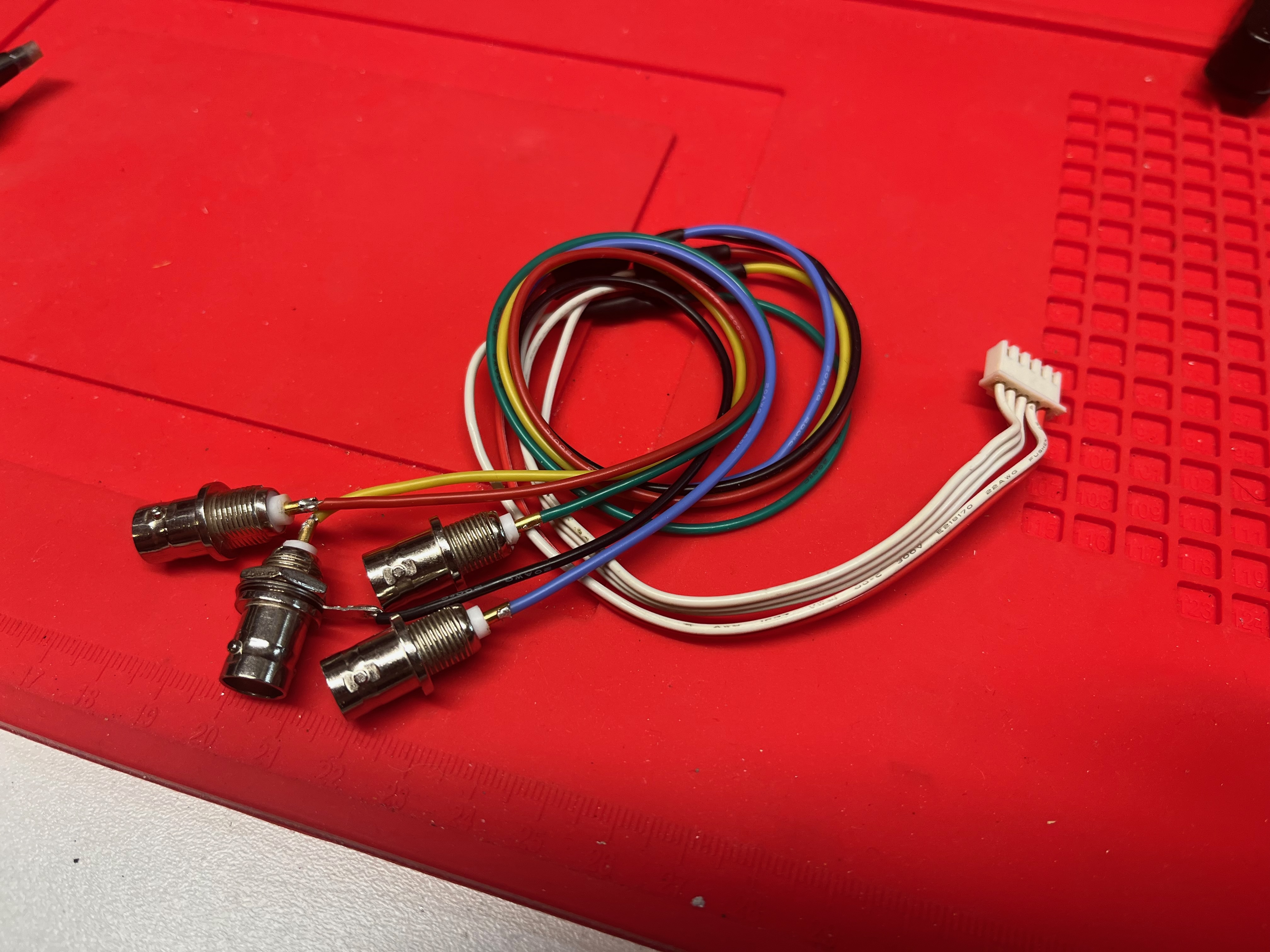
And just like that, we have an RGBS input!
Step 2 - Add the RGBS / CVBS switch
There’s a stenciled switch labeled “CVBS / RGB” on the silkscreen near the size adjustments on the main board. When present on the board, this switch toggles between the composite / S-Video input and the RGB input. Tracing out the circuit a bit, I believe this switch does two things in the RGB position: it enables the RGB blanking, and connects the composite sync line from the RGB input to the jungle chip via a separate mux. Populating this switch will restore the RGB input.
It’s a 6 pin DPDT switch, which is not something I had on hand. Rather than order one, I decided to repurpose the “75 ohm / HI Z” switch. After moving that switch over, I bridged the connection to permanently select 75 ohm mode which effectively disables the composite video passthrough. Replacing those jumpers with another switch would restore full functionality, but I don’t need the passthrough for now.

With the switch in place and the RGB input connected, the monitor is now fully RGB capable!
Step 3 - Modding the case
To finish off the mod, I drilled holes in the rear panel and mounted my BNC jacks. My technique needs some improvement here, as I was drilling the bit had a tendency to wander and throw off the alignment of the holes…
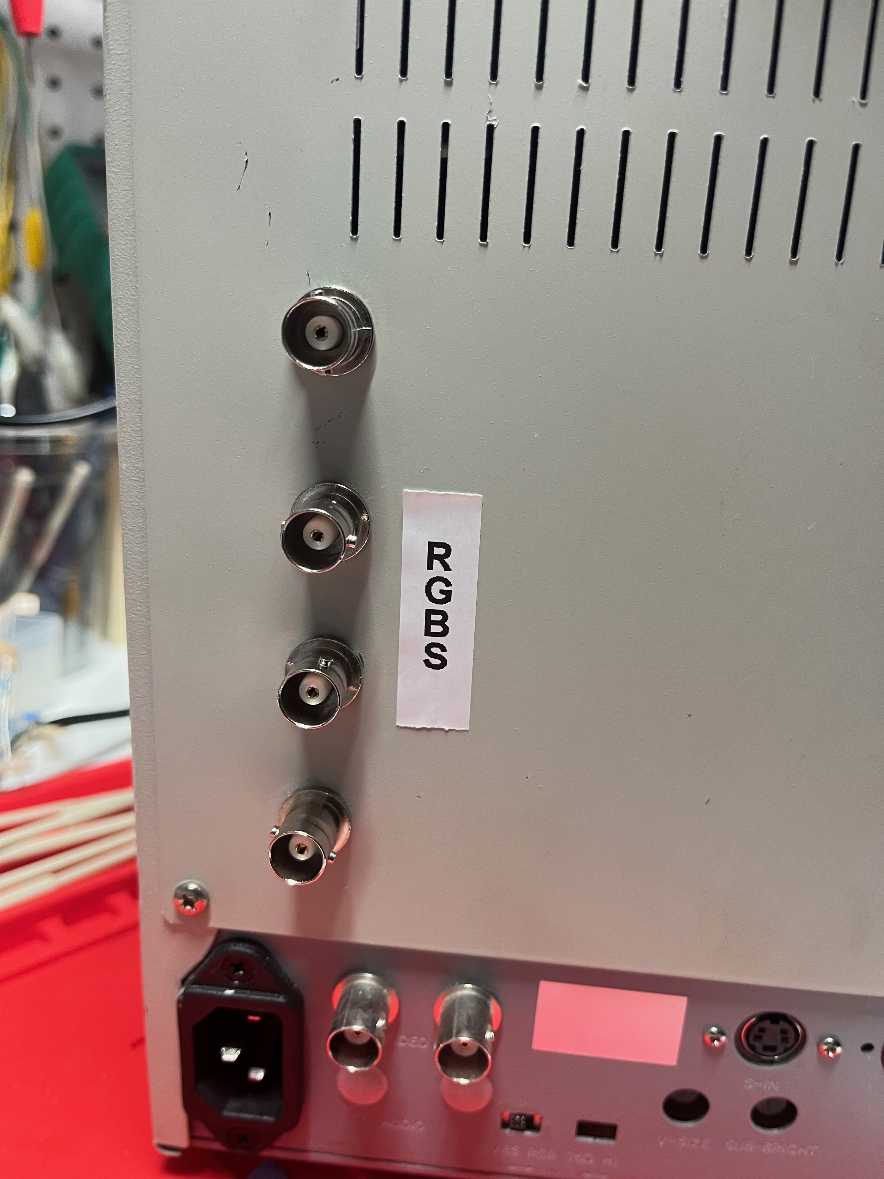
But it works! Good enough for the work bench.
The results
This monitor has a very sharp picture over RGB! The CRT is able to resolve a surprising amount of detail despite the small size. I’ve been using it to play a few classic arcade games, and the colors really pop:

Tate mode looks great as well:

However, there is one issue… this monitor displays a strange yellow trail following red content. This is perhaps better described as yellow fringing around red. It’s a very small defect; looking close, it appears as though one extra column of phosphor dots is ignited at the right edge of any red on the screen. This would be the green phosphor, which explains the yellow appearance of the trail.

I’ve never seen anything like this before! I retested the composite and S-video input and sure enough, that yellow trail is there as well, just far less noticeable due to the overall blur of the image. I have no idea how or why this happens, I’m just going to accept it as a quirk of this particular monitor…